Designed by GOEMO.de
Copyright © 2013 by "Rainer Sobottka www.ir-engineering.com" • All Rights reserved • E-Mail: consultantir-engineering.com
thermal imaging in chemical plant at hotspot-POX reactors, substations, leakdetection and many more
ir-engineering.com
Application-1 POX Reactor
Application Example 1: POX Reactor, Gasifier
Reactors, such as gasifier, run a process inside with extreme hot temperatures near design limits. The hot temperatures inside require a special refractory lining to eliminate heat transfer from inside to the outer metal shell (steel design temp. 450 degr.C typically). Oil, gas, and coal gasification run temperatures of up to 1450 degr. C ( degr. F). Other reactors may run temperatures of 800 to 1300 degrees C. Reactors are used for many different plants such as residual oil gasification, coal gasification, other type of gasification, biomass gasifiers, sulphur reactors, and many others.
Older technologies do not allow reliable temperature measurements and no graphical analysis. In addition, mechanical problems like refractory movements, broken elements, gaps, and mechanic limitations give reasons for not reliable measurements. The industry of temperature sensors still run good business with continuous supply of such elements which often fail, break, or give false readings at continuous drifting values. Plant user`s maintenance group must store many spare elements in stock for replacements whenever needed. Disturbance in temperature measurements have caused many shut down and loss of production. Temperature measurements inside the reactor as well as at the outer shell are still a key issue for improvements and still give danger for shut down.
However, this was the case up to 2001 only. The outer skin temperature system now has been changed to a total different technology with very high reliability and accuracy. It’s a kind of revolution in skin measurement, especially for gasification reactors. Infrared continuous monitoring cameras have replaced the doubtful and altering cable systems.
The invention of using infrared camera systems for scanning temperatures have all of a sudden eliminated the subject from “not reliable measurements” now changed to “extreme accurate and reliable measurements”. Temperature profiles, gasifier monitoring, gasifier temperature skin measurement, infrared hot spot measurements, now are available for safety and shut down systems, and it require almost no maintenance, no purchase of spare elements, no stock holding spares. The use of infrared gasification camera is a very common subject now, many plants have exchanged their “not reliable” cable system to accurate infrared measurements, to accurate infrared hotspot measurement, to infrared continuous monitoring, and to infrared gasification cameras.
Technology Concepts:
Please read the previous pages of “Technology” and “Basics” to read about technical details.
Benefits:
Savings of maintenance personnel: almost none maintenance required
this is a huge saving, as earlier maintenance personnel was always and continuously busy with checking, adjusting, removing, repairing, and it was a huge impact during shut down periods where the entire cable system had to be removed and to be re-installed for repairs on gasifiers. The infrared camera system is installed remote and far away of reactor, but in direct sight/view.
Savings of spares and no additional procurements: almost none spare parts required. The field equipment is minor in quantity and quality and long lasting, the cameras and housing are extreme reliable and proven, first infrared camera system installation still running today with same hardware equipment, no maintenance after almost 10 years!
Savings Engineering: no special design required during engineering and first procurement of vessel and instruments. Design, Inquiry and procurement can be executed at end of engineering.
Savings in Gasifier Design: no requirement of special rails and bolts welded on the vessel (saving of approximately 120,000.-$), no clarification/delay during start of engineering to order this log lead item of gasifier vessel. There is no requirement at all for the vessel itself when using infrared cameras instead of any cable system.
Savings in Installation: no special requirement of hardware or connectors. Each field contractor can erect all hardware easily and in short time. Positioning of cameras is as per photographs taken with normal digital camera in same lens and chip attributes (if not the same, then can be calculated once for all). Plant user’s standard contractor can execute such installations.
Savings in Commissioning: no special requirement and procedure. Just switch on the stand alone unit and see images and data recording on monitor. Special care only required for link and transfer to other computer systems if desired by client. Plant user’s standard contractor or plant user himself can execute such commissioning.
Savings in Operation: no special training or operation required. All kind
of personnel can operate and use/analyse data from the stand computer alone system. No instrument support/maintenance required.
Savings in Costs: Adding all of above, the use of infrared camera system is cheaper than conventional cable system. Please consider the overall costs, not the cost of single equipment such as cameras to cables. The cost savings in engineering and vessel design alone is so much that the slightly higher cost of the cameras is already compensated.
Please contact us for more details and results of our experience in engineering, commissioning and operation of such equipment, cable system as well as infrared camera system of different brand/manufacturer: consulting@ir-engineering.com
Temperature Reading Resolution and Accuracy
The infrared gasification cameras used for reactors give extreme reliable and very accurate temperature reassigns, not only for hotspot measurement but also for scanning exact temperatures all over the vessel skin. The infrared hotspot measurement gives readings of approx.. 70.000 single temperature measurements per image taken. Images are scanned at a rate of 1 per minute and in case the alarm value is reached the scanning rate switches automatically to a higher rate of 1 per second or other, as per your configuration.
This infrared continuous monitoring system records all data and it give display of trend, profile, average, deviation, and all kind of other values and data as per your plant requirement. Operators can easily spot the exact situation of the reactor and they can conclude from outside graphics to the inside refractory status.
The infrared gasification camera transfers a huge amount of temperature data to your monitors in the control room. It is up to you and your configuration to put your priority data on top display or forward all archiving data to your management.
It is possible now to
Read single temperatures continuously of your vessel surface
Display data and temperature values in resolution of a few millimetres of your vessel skin
Move your computer mouse over the vessel image and read actual temperature values
All data are automatically recorded in the background and you can re-call all data whenever required (archiving)
Alarm system will display alarm points, alert situations, deviations to critical areas/temperatures
Hotspot measurement will show you continuously the hottest point, the lowest point, and the average value of areas defined in your configuration
Infrared hotspot monitoring will record videos of your vessel skin and you can recall the same from the past to spot developments of increasing temperature points on the skin of your reactor, means first indication of a damaged refractor, means very early you are able to control your feed and operation not to damage the refractory
Establish your own analyzis, profile, trends, and history records for operation, engineering, process, and management
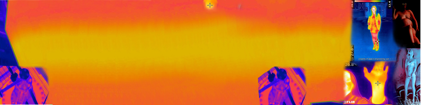
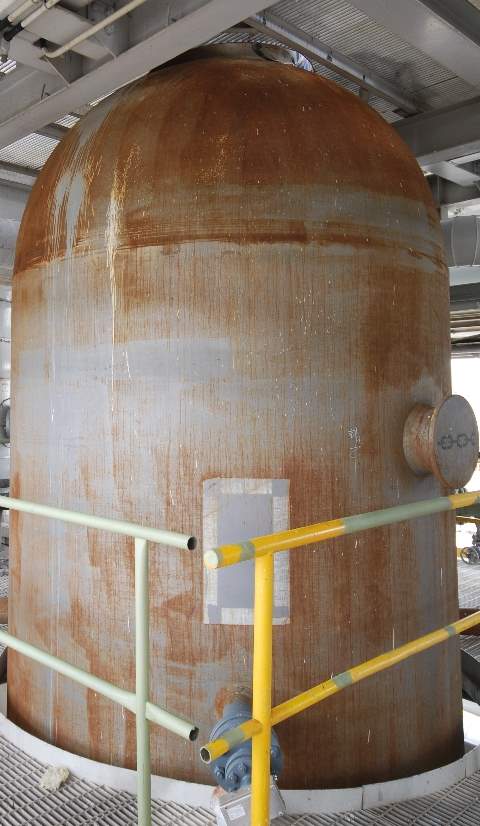
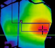
Concept of resolution prepared with your home digital camera:
Concept of resolution prepared with your home digital camera: standard lens is f=80 mm
distance from camera to reactor is 6 meters
then your picture is approximately this one left:
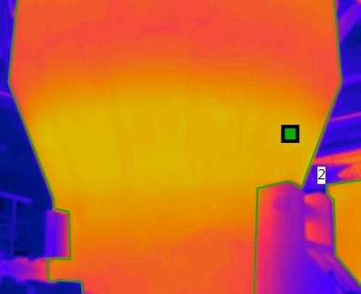
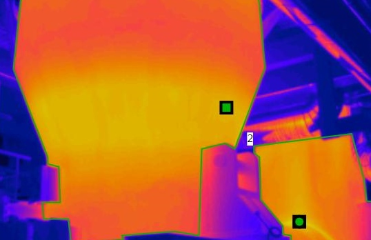
right: the picture taken with the infrared camera
The infrared image has 240x320 pixels, each pixel corresponds to one individual temperature measurement). All together for one image there are over 70 000 pixels, or over 70 000 single temperature measuring point.
The color of the image can be selected/configured as per requirement; green for normal temperatures, red for alert
Control Room Installation
Please read the previous pages of “Technology” and “Basics” to read about technical details
When not using the stand alone system of the manufacturer then additional configuration work is required at DCS or ESD system.
Commissioning
After checks of installation, grounding, connections, etc. the system can be powered on directly. After automatic booting the configuration screen will show up on the screen. Standard values for emission factor, etc. shall be checked. The position, the focus, and the screen area shall be checked and adjusted if required.
The entire procedure will take one day if not other disturbances appear.
Under normal circumstances the entire installation work and commissioning work can be executed by local personnel when reading the corresponding manuals and proceed accordingly.
No special know-how or training is required for any of the personnel in the control room normally working.
Reference Clients and Installations
Origin: Rainer Sobottka
Origin: Rainer Sobottka

Infrared Imaging in private sectors


